Providing Innovative State-of–the-Art Test Equipment For the Aviation Industry
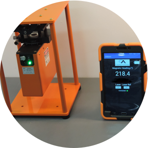
CA-320/321 LEGACY
DIGITAL COMPASS
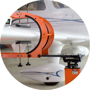
This stand-alone, portable, magnetic measurement standard replaces the need for a compass rose, master sight compass, surveyor transit devices and complex specialized equipment.
We are a vertically integrated company with the engineering talent and industry expertise to provide all levels of support for our customers – from inception to the finished product – with a legacy of Quality, Service and Innovation.